Fabrics
Fabrics are isolated, self-contained arrangements of network interconnections that form a topology, including the switches, links, and logical structure.
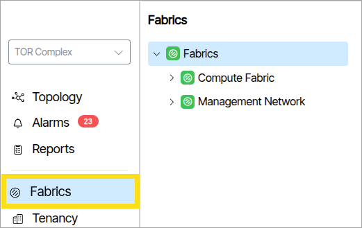
The Fabrics window gives administrators an overview of each Fabric that the Verity instance references. Verity displays the objects in a collapsible tree view.
Colors🔗
- The default color for a disabled fabric object is grey.
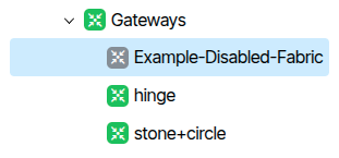
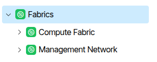
- The default color for an enabled working fabric object is green.
Alarm Colors🔗
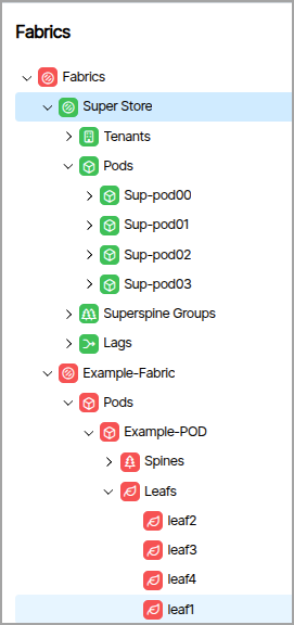
When an object triggers an alarm, its icon changes to the alarm's color 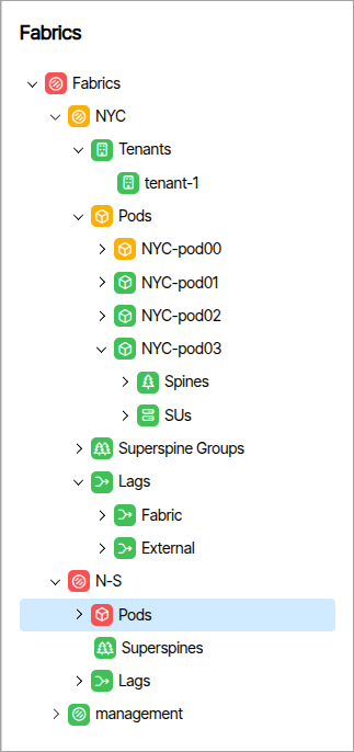 . The color change cascades up the hierarchy, always reflecting the most severe active alarm at each level. In the image below, the Fabric named Example-Fabric has Leafs triggering a Severe (red) alarm. This notification cascades through the entire hierarchy to the Fabric's parent. In the image below, the Fabric named Super Store is a completely independent Fabric and remains unaffected by the other Fabrics' alarm events.
How to Create a Fabric🔗
To create a Fabric, select the parent Fabric tree object and click the Add Fabric button. A form appears requiring a name for the Fabric and a Fabric type. Fill in the fields and click Add Fabric (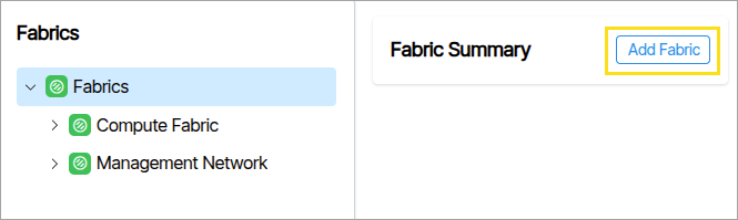 ).
).
The hierarchical object components display differently depending on the fabric type. The tree contains nodes that represent fabrics, categories for switch devices (LAGs, Pods, SuperSpines, Leafs, etc.), and the switch devices themselves.
Fabric Types🔗
Management
A switch network providing connectivity to the out-of-band management ports of switches across the other fabrics.
- Fabrics
- Management-Example
- Switches
- Management-Example
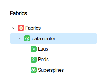
Data Center 3 Stage Clos
Spine-Leaf network configuration where traffic traverses three switch hops — leaf → spine → leaf — within a single POD.
- Fabrics
- Data-Center-3-Example
- Lags
- PODs
- Super Spines
- Data-Center-3-Example
Multiplane
- Fabrics
- Multiplane-Example
- Lags
- PODs
- Spine Planes
- Multiplane-Example
Packet Broker
A Packet Broker is a network device placed between network traffic sources and monitoring tools (or other destinations).
- Fabrics
- Packet-Broker-Example
- Egress
- Ingress
- Packet-Broker-Example
Spectrum-X 2 Tier
NVIDIA Spectrum-X Ethernet networking platform. Can be configured as a multi-plane system for increased redundancy and scale.
- Fabrics
- Spectrum-X-2-Tier-Example
- Spines
- SUs
- Spectrum-X-2-Tier-Example
Spectrum-X 3 Tier
NVIDIA Spectrum-X Ethernet networking platform. Can be configured as a multi-plane system for increased redundancy and scale.
- Fabrics
- Data-Center-3-Example
- PODs
- Superspine Groups
- Data-Center-3-Example
Data Center 5 Stage Clos
Spine-Leaf network configuration traversing five hops — leaf → spine → superspine → spine → leaf — across multiple PODs. Superspines interconnect PODs for non-blocking any-to-any connectivity.
- Fabrics
- Data-Center-3-Example
- Lags
- PODs
- Superspines
- Data-Center-3-Example
Inspector Window Object Details🔗
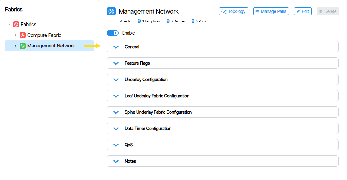
The inspector window to the right reveals information and parameters of the selected tree object.
Fabric Details🔗
Fabric objects have customizable fields that appear when you click them.
Managed Pairs🔗
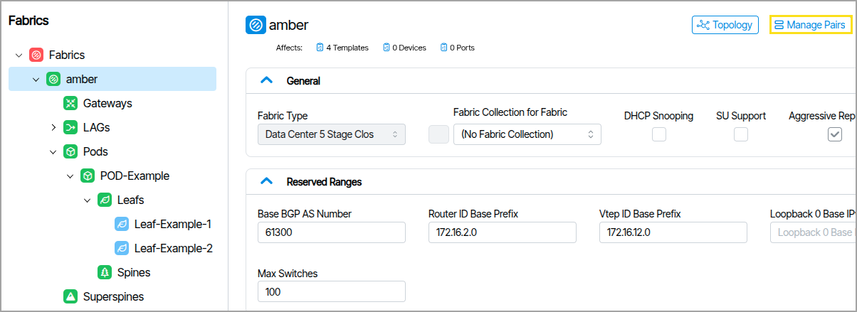
The Managed Pairs button ( ) opens a window that lets you manage and create Switch Pairs, also called Redundancy Pairs
 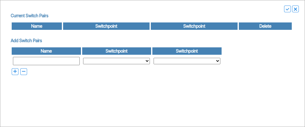 .
.
General🔗
Fabric Type and other settings including DHCP Snooping.
Reserved Ranges🔗
Provisioning reserved ranges specific to the fabric are listed here. Other Reserved Ranges are available in Admin → System → Reserved Ranges
Feature Flags🔗
This section lists additional configuration options including settings to allow underlay connections between Pods, port admin and port status interval values.
Underlay Configuration🔗
Manages fundamental network infrastructure settings, including a shared Anycast MAC address for redundancy and load balancing. It controls how network devices handle address aging and connection restoration, ensuring stable and efficient baseline network communication.
Leaf Underlay Fabric Configuration🔗
These settings control how leaf devices establish and maintain BGP connections, including timing for connection checks, routing updates, and connection establishment, ensuring stable and responsive network edge communications.
Spine Underlay Fabric Configuration🔗
Defines how spine devices maintain and establish BGP (Border Gateway Protocol) connections. These settings manage network behaviors such as connection keepalive intervals, connection timeout periods, and routing information exchange.
Data Timer Configuration🔗
Provides advanced timing controls that optimize connection stability and performance. These settings allow network administrators to fine-tune how devices handle interface state changes, link detection, and MAC address management. By adjusting Link State Timeout, Startup Delay, and MAC Holdtime, users can customize network resilience and reduce unnecessary connection disruptions.
QoS🔗
DSCP to TC Map🔗
DSCP to TC Map is a translation table that converts quality-of-service markings between two different systems. This feature maps incoming DSCP priority markings (0-63) to internal Traffic Class queues (0-7) to ensure high-priority traffic like voice and video receives proper handling.
Click the Priority numbers below the DSCP numbers (image needed) to choose the range of numbers to set (image needed).
Notes🔗
A persistent note writing section for administrators.
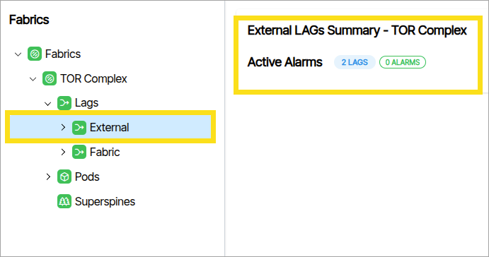
Container Details🔗
Some tree view items exist only to group their children. Clicking these nodes reveals aggregate details about the child objects. The following image shows that the node named External contains 2 LAGs and no alarms.
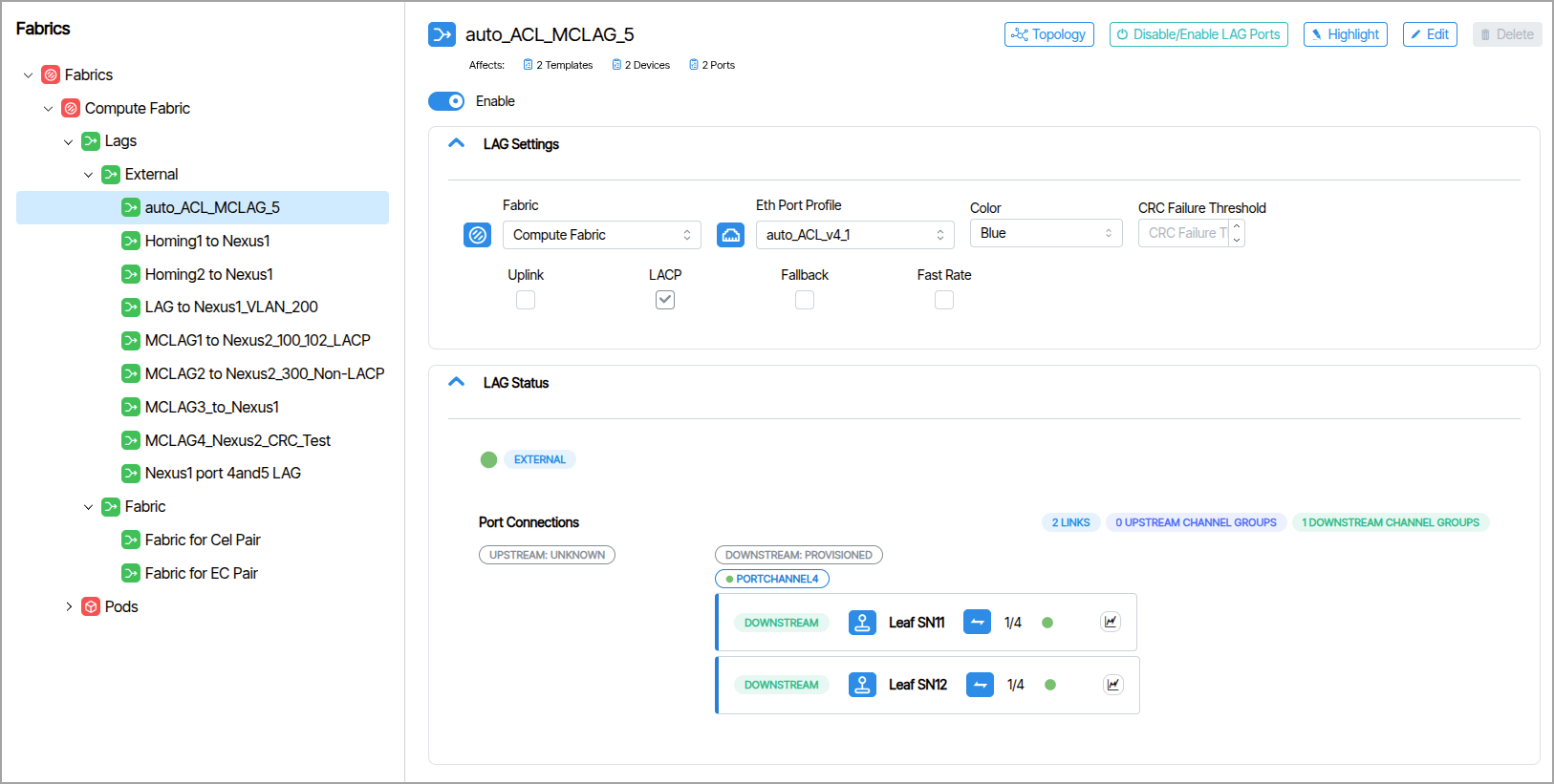
LAGs (Fabric/External)🔗
You view and manage LAG parameters from the Fabrics navigation window.
Fabric LAG Parameters🔗
External LAG Parameters🔗
Switches (Spine,Leafs)🔗
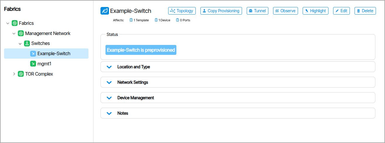
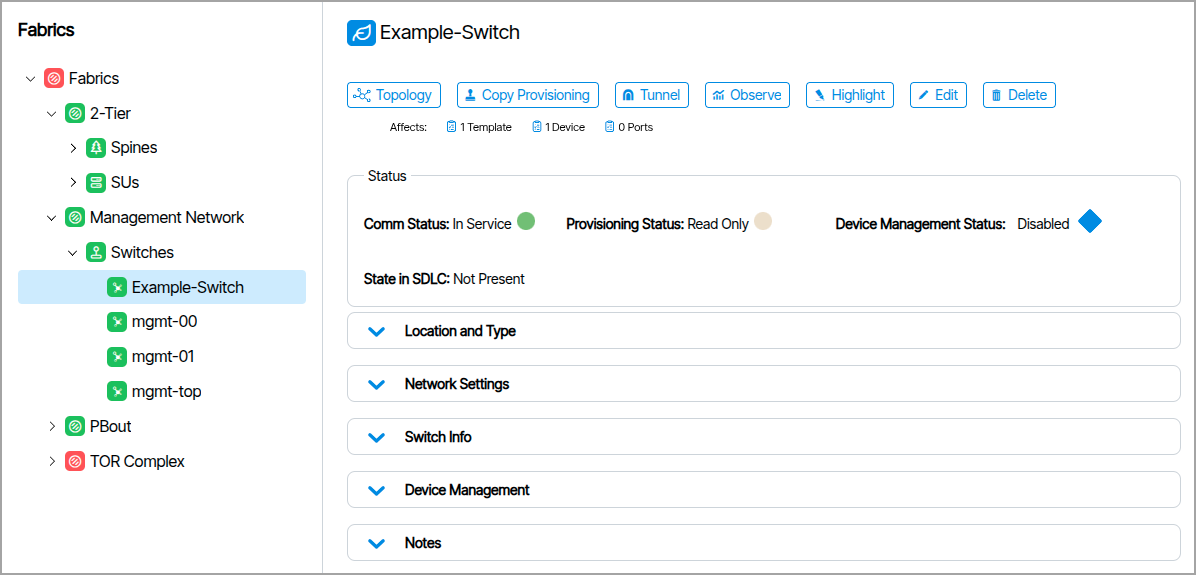
Status🔗
These indicators provide information about the device state.
-
Comm Status: Indicates the overall communication health and connectivity state of the device within the Beyond Edge management system.
-
Provisioning Status: Indicates the current provisioning state.
-
Device Management Status: When you enable Device Management parameters, this indicates the connection status.
-
State in SDLC: Indicates SDLC behavior.
Location and Type🔗
Type of device (Spine, Leaf, Superspine, Management) , POD and Rack information is listed here.
Network Settings🔗
Network Settings vary depending on the device type.
Switch Info🔗
Switch Info displays device hardware details, such as make and model, and basic configuration information, including the current management IP address. This information is also viewable from Topology at the top of Switch (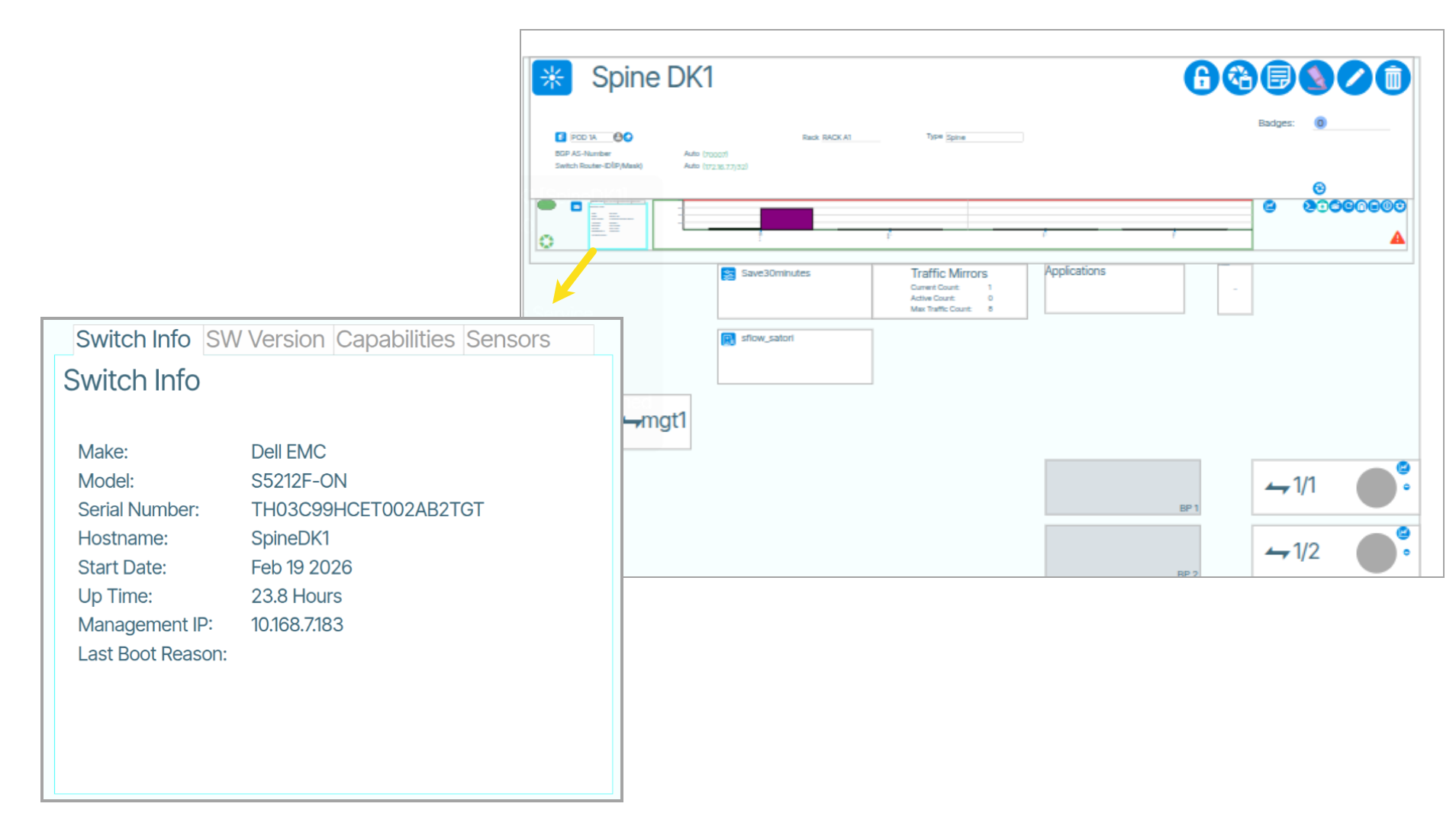 ).
).
Device Management🔗
Device Management settings are editable and fall under Switchpoint settings. In addition to the parameters in Device Management, Switchpoint settings include all port provisioning of the switch. You can copy these values between devices using the Copy Provisioning feature.
How to Create a Switch Pair From Fabrics🔗
-
Determine the target devices. If the target devices do not yet exist, create them before creating a switch pair.
-
Select the containing network Fabric.
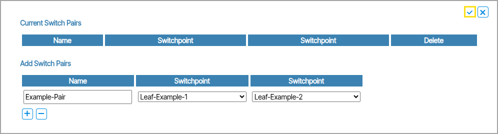
- In the upper right of the page, click Manage Pairs.
- Enter a name in the Name field, then select your devices under the Switchpoint fields.
- Make physical connection. The ports must be configured identically and operate at the same speed.
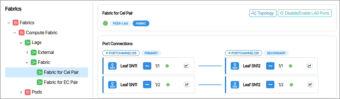
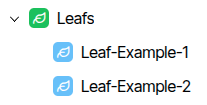
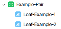
When complete, the Fabrics tree displays the devices as a related pair with the Switch Pair icon.
How to Create a Fabric Gateway🔗
A Fabric Gateway represents each end of a planned BGP session between fabrics. For high availability, four fabric gateways are needed — one for each end of each session.
- From Fabrics, select the Fabric.
- Select Gateways.
- In the upper right corner, click Add Gateway.
Configure each Gateway object with the following:
- The Neighbor AS number of the remote Leaf switch
- The IP address assigned to the Gateway Port Profile on that neighbor's switch
- The Fabric Interconnect option enabled
Gateway Modes🔗🔗
Gateways can be one of several different modes. The Gateway Mode field defines how the software handles and routes traffic within the network. It determines whether routing decisions are based on a statically defined default gateway, static routes, traditional BGP routing, or new enhancements to BGP to support dynamic neighbors.
- Default: A single static default route.
- Static: Uses manually configured static routes, no dynamic routing.
- Static BGP: Establishes BGP sessions with manually configured BGP neighbors. The BGP neighbors are explicitly defined by their IP addresses, and no dynamic peer discovery occurs within the subnet.
- Dynamic BGP: BGP neighbors are dynamically discovered within a subnet, leading to the creation of multiple BGP sessions from a single tenant gateway object.