Link Aggregation (LAGs)🔗
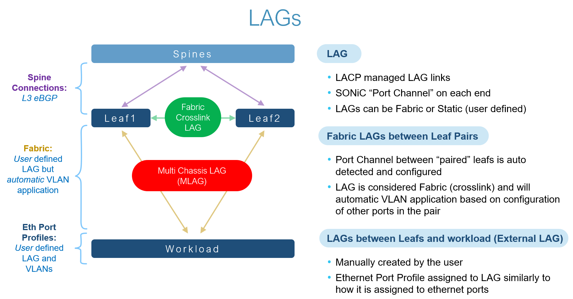
Link aggregation is a popular method for grouping multiple ethernet connections into a single logical link. Traffic across this link is automatically load balanced across the grouped (bonded) links. LAGs can extend from single leaf switches or can be configured across a pair of leaf switches. When a leaf pair is created and LAGs are assigned to ports on each switch, the LAG is considered an "MLAG". MLAG, or Multi-chassis Link Aggregation, is a networking technology that aggregates multiple physical ports across two or more switches into a single logical link, thereby providing increased bandwidth, redundancy, and resilience. This allows servers and other network devices to connect to different switches and appear as if they are connected to a single switch, improving network performance and fault tolerance.
Automation
The interconnect between Leaf Pairs (Fabric Crosslink LAG shown in diagram below) is automatically recognized and configured by Verity. This section explains how to create external LAG connections to the workload.
Link Aggregation Process🔗
Although there are several ways of completing the process, an easy to understand method requires these steps:
- Identify the composition of the LAG, including the leaf pairs and ports you intend to use in its configuration. (Assuming you are implementing MLAG)
- Create the external LAG object, name it, and assign it to the port(s).
- Select the Tenant services and create an Eth Port profile and assign it to the external LAG.

The following example below shows how to create an external LAG relationship between two leaf ports. These actions can be used to establish different LAG configurations depending on your needs, such as aggregating multiple ports on a single leaf switch to boost endpoint bandwidth.
Identify Switches and Ports for a new LAG🔗
To create the external LAG, you first need to identify the switches and ports you plan to use. For this demonstration, we will refer to these switches as Leaf-1 and Leaf-2, but you can choose any switches (and ports) to configure as a LAG.
Manually Creating a Switch Pair.🔗
- Determine the two Leaf switches to be paired and identify the connecting ports on both.
- On the Main Navigation Bar, select Topology.
- Select Network View.From the upper right of the Network View window click the Manage Switch Pairs button (
 ).
). - Enter a name for the switch pair.
- Assign the first Leaf to the first column under the Switchpoint section, and the second Leaf to the second column.
- After naming and assigning the switches, click the Save button.
- Make physical connection. The ports must be configured identically and operate at the same speed.
Create and Assign the LAG to Ports🔗
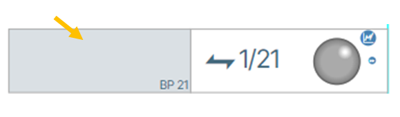
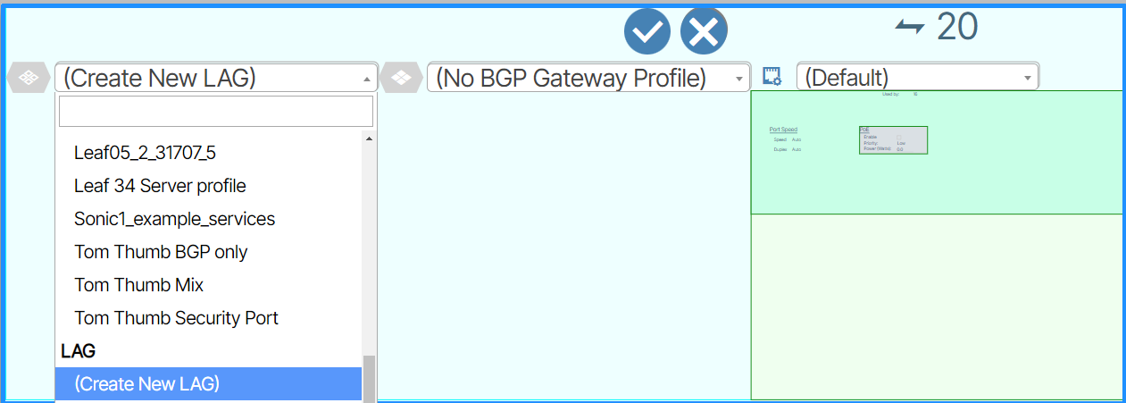
- Select a port on your chosen device (we call this Leaf-1) and zoom in on it. Open its parameters by clicking the space to the left of the dividing line.
- Click the Edit (
 ) button. On the left drop-down menu, select Create New LAG.
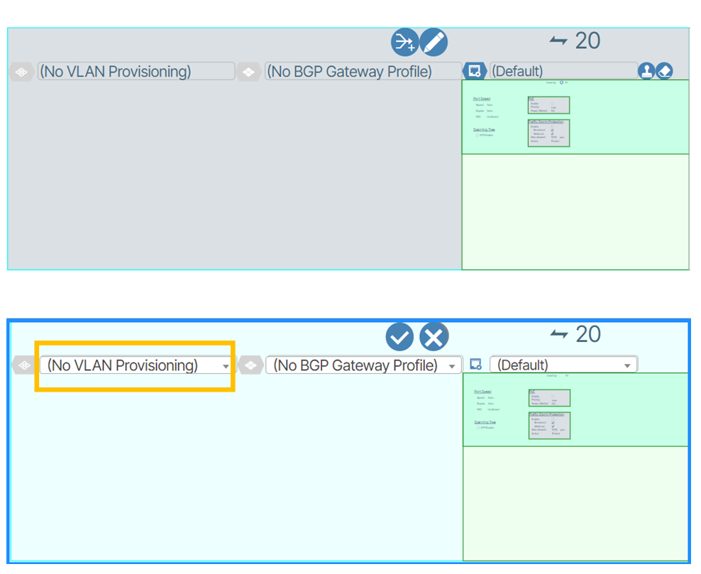
- Click the Save button (
 ) to save your work.
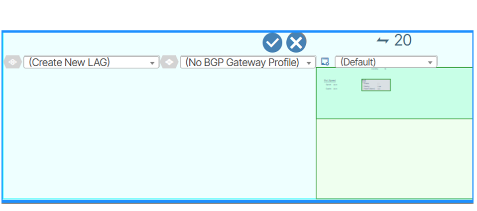
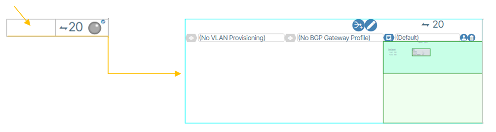
- Click the hex button (
 ) to jump to the LAG parameters.
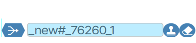
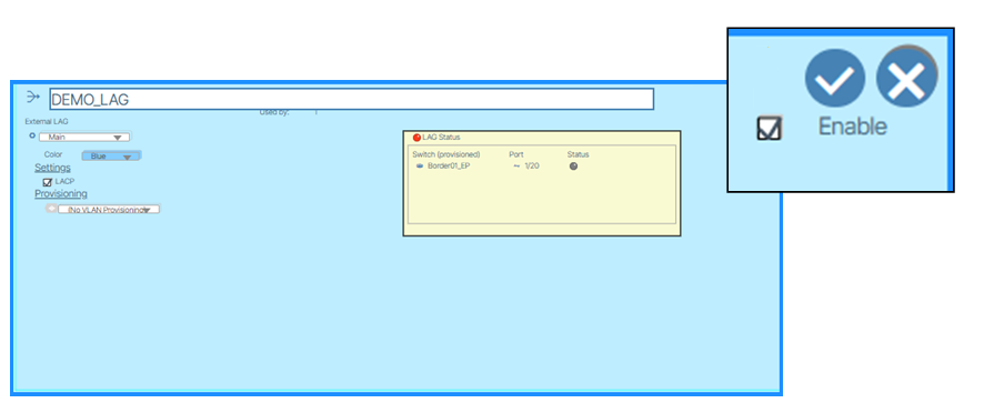
- Click the Edit button () and change the name of the LAG to meaningfully distinguish it.
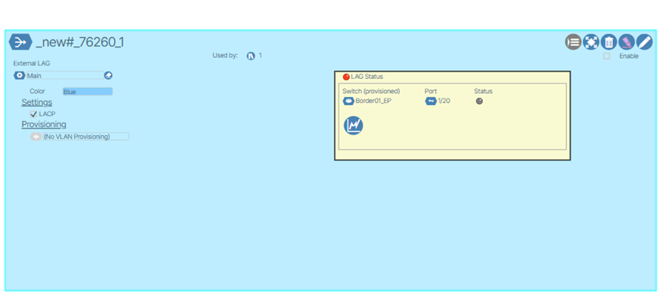
- Check the Enable box and then click the Save button () to save your changes.
Assign LAG to Second Switch Port🔗
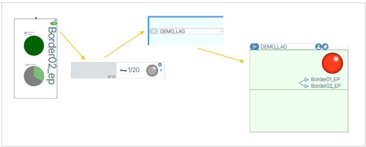
- On the second chosen switch in the pair (we call this Leaf-2) select the desired port (such as port-2) and open the Provision Port settings. Enable editing by clicking the editing button.
- In the first form field set the name of the LAG you previously created.
- Click the Save button to save your work.
- Select the desired options and set the desired values to those options.
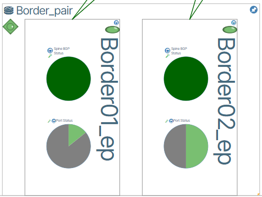
Validate LAG Status Display🔗
- As the system creates the channel groups and communicates over LACP, there will be a delay in the system for up to 5 minutes, after which the status display will turn green
 .
. - If you encounter problems and the icon remains red or yellow, hovering over the status icon provides more information
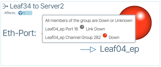 .
.
Assign Services to the LAG via Provisioning Settings🔗
There are multiple ways to assign Services to LAGs. The primary method is via the LAGs Provisioning settings. As previously shown, you can navigate to LAG settings via a switch port by clicking the port and then clicking the LAGs hex button. It is also possible to view External LAGs parameters from Network View via the process demonstrated here:

Settings🔗

- Uplink
- LACP
- Fallback
- Fast Rate
In the Provisioning drop-down menu, assign an Eth Port Profile. As mentioned earlier, an Eth Port Profile is a collection of Services 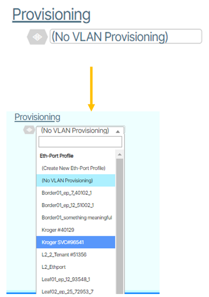 .
.
Assign Services to the LAG via “Add LAG” Button🔗
- Zoom into the settings of a port you want to assign the LAG to
 .
. - Click the Add LAG button (
 )
) 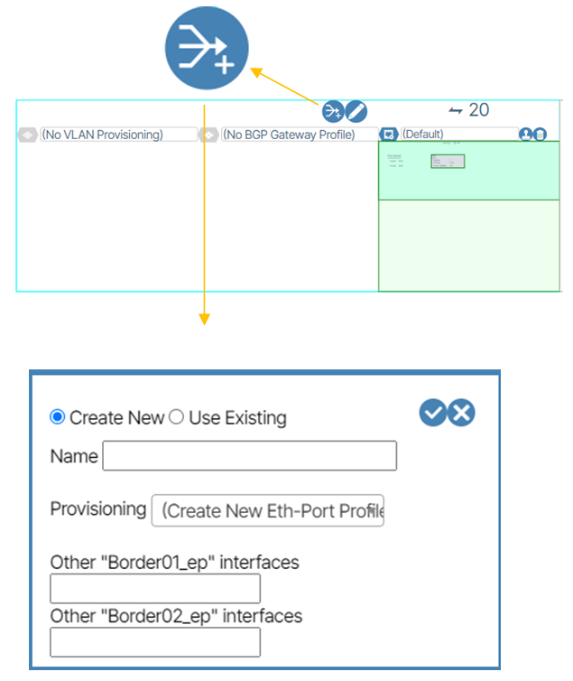 .
. - Fill out the form with the following LAG settings:
| Setting | Description |
|---|---|
| Create New / Use Existing | Determines if you are creating a LAG or using an existing LAG. If you choose Use Existing, the form field presents you with a list of existing LAGs to choose from. |
| Name | Sets the name of the LAG. |
| Provisioning | The Eth Port Profile (the service(s)) you assign to the LAG. |
| Other 1 | The port number(s) (separated by commas if more than one) of the listed switch to assign the LAG to. |
| Other 2 | The port number(s) (separated by commas if more than one) of the listed switch to assign the LAG to. |
Provision Channel Group Endpoints and Set Physical Connections🔗
The next step is to provision channel endpoints. This step is outside the scope of these instructions. The last step in the process is to physically connect the devices.
ESI Multihoming🔗
A ESI Multihoming is a networking technology that allows multiple switches (typically leaf switches in a data center network) to form a single logical link aggregation group (LAG). Its configuration closely resembles that of a switch-pair MLAG, with the key distinction being the inclusion of up to four switches, significantly enhancing network redundancy and scalability. The number of ports that can be assigned a Multihoming ESI group is indeterminate. The number of switch devices is limited to four.
ESI vs MLAG
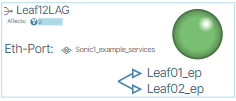
In Verity, LAGS assigned to two or more non-paired Leaf Switches use ESI Multihoming protocol instead of proprietary MLAG implementations. Multihoming is a feature that is automatically enabled, requiring no setup from the customer.
If a LAG is using ESI Multihoming, it will display text that says Multihoming.

Relationship to Leaf Pairs🔗
The multihoming feature is implicitly disabled on all leaf switches configured as leaf-pairs. Any leaf with multihoming in use cannot be made part of a leaf pair until the multihoming configuration is removed. This prevents any conflict between the MLAG functionality on leaf pairs and the multihoming functionality.
Conflict Resolution🔗
When attempting to pair a Multihoming switch, a conflict arises, and an error message is displayed that gives you the choice to disconnect the Multihoming connection(s).