Device Management🔗
This section explains how to onboard devices to a Verity system. The most efficient approach for creating the system intiially is to use the bulk configuration method via a system initialization file. However, devices can also be onboarded individually through the Verity UI.
Adding Individual Devices🔗
Note
This section describes how to manually add devices to the system. To add devices in bulk please see the section titled Onboarding Devices in Bulk
Adding a new spine or leaf device is a multi-step process described by the following steps:

- Create or select the provisioning object.
- Create the device controller and assign a switchpoint.
- Prepare the physical switch.
- Boot the device.
- Connect the switch to the peers.
Preprovision Object Creation🔗
Preprovisioning lets the user set up the device before the hardware arrives. Zooming in allows the user to edit the details of the device.

Adding Leaf or Spine Devices🔗
- Enable the world view by clicking the World icon (
 ) .
) . - Click the Topology (
 ) icon.
 - Click the menu tab labeled Topology.
- Click the Add Preprovisioned Switch (
 ) icon.
 - Enter the name of the switch.
- Set the number of Expected Eth Ports.
- Set the Rack text (Optional).
- Click-hold the Type field and select Leaf, Spine, Superspine or Management.
- If the switchpoint is designated as a Leaf or Spine, Click hold the POD field and set its value.
The following section describes other switchpoint management features. These are not required for device onboarding, but do give the user the ability to create provisioning for the switchpoint before the phyical device is detected and brought into the system. To proceed with the new device creation skip to the Device controller section below.
Manage Rows Button🔗
![]()
The Manage Rows button ( ) provides a convenient way to apply the same settings to multiple ports on a single switch. The settings include switch provisioning as well as the mass enabling/disabling of Edge ports.
Set Eth-Port Provisioning🔗
This option lets you choose an Eth-Port Profile and apply it to a port or to a consecutive list of ports. 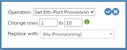
Set Eth-Port Setting🔗
This option lets you choose an Eth-Port Setting and apply it to a port or to a consecutive list of ports. 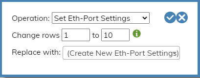
Replace Eth-Port Provisioning🔗
This option lets you choose all ports by their assigned Eth-Port Profile and replace the assignment with a different Eth-Port Profile. 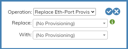
Replace Eth-Port Settings🔗
This option lets you choose all ports by their assigned Eth-Port Setting and replace the assignment with a different Eth-Port Setting. 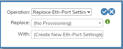
Clear All🔗
This setting clears Eth-Port Provisioning values and sets Eth-Port Profiles to default for a port or a consecutive list of ports. 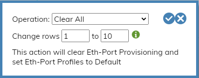
Enable Edge Ports🔗
This setting lets you enable an Edge Port or enable a consecutive list of Edge Ports. 
Disable Edge Ports🔗
This setting lets you disable an Edge Port or disable a consecutive list of Edge Ports. 
Enable or Disable Individual Device Port🔗
To enable or disable an individual port, zoom in on the port and click the Enabled checkbox to set the desired state.

Device Controller🔗
The Device Controllers object is used to create the interface between the Verity application and the switch device. Based on the LLDP capabilities of the switch, it can be automatically discovered in the network topology, or it can be statically located. For systems containing many devices, the configuration of the Device Controllers can be imported/exported from the Import/Export tool bench. 
Create a Device Controller🔗
- From the world view, click Admin icon.
- In the menu bar, click VNFs.
- In the Device Controller tile, click the plus button (
 ) to create a new Device Controller.
 - Type a name for the Device Controller. Push Enter and the new Device Controller edit window will appear.
- Click the Edit button (
 ) and the required fields are displayed in red highlights.
  .
. - Enter the LLDP Search String content. This value must be either the chassis ID or the serial number of the managed device. This value serves as a hardware identifier and is used to detect connections between managed devices. Later, this value will auto-populate in the pre-provisioned Device ID when the entries to the Device Controller are saved (this is verified in step 11).
- Enter the Switch IP and Mask.
- Enter the Gateway.
Assign the Switchpoint🔗
A Switchpoint is a logical location for a device in the network and represents a connection point—such as where leaf 1 connects to spine 3. By designing a network using Switchpoints, the logical design remains independent of specific devices, allowing an operator to insert a device into the switchpoint by referring to either its serial number or a chassis id.
-
While editing the Device Controller, select the Switchpoint field and assign a Switchpoint.

-
Enable the Device Controller and save the changes.
-
Verify the Hardware Identifier. The Device Controller LLDP Search String should appear on the switchpoint provisioning object in the Device ID field.

How Switch Hostnames are provisioned

Each Device Controller includes both an LLDP Search String and a ZTP Identifier field. How these fields are populated determines how the hostname is assigned to the device. The hostname can be the set to the switchpoint name or to a hardware identifier (serial number or chassis ID).
- If only the LLDP Search String is entered and the ZTP Identifier is left blank, Verity uses the LLDP Search String to create ZTP files, set the hostname and identify the device durining network topology discovery.
- If both fields are filled with different values, the ZTP Identifier is used to create ZTP files, the LLDP chassis ID is used to identify the device during network topology discovery, and the hostname is set to the switchpoint name.
Physical Switch Preparation and Connection.🔗
New Devices Starting Point
It is required that all SONiC devices being onboarded into Verity start in ONIE mode with no OS installed. This ensures that the device receives its load from the Partner Firmware Package installed on Verity and runs through the ZTP process. (If the current switch is running OS10 with DHCP enabled, OS10 is automatically removed when using DHCP options set up according to this documentation.)
When ready, connect the management port of the new device to the Out-of-Band Management network. Then, connect the device to the other relevant spine/leaf switches needed to integrate the device into the system.
Zero Touch Provisioning🔗
Verity’s ZTP feature is a way to remotely set up switches without having to manually configure them on a hop-by-hop basis. The process consists of two steps: ONIE Boot process and ZTP Provisioning portion.
The ONIE process starts when a switch boots up from the factory without a SONiC image and it connects to a remote server to download the necessary software image. The actual ZTP process starts with a switch that has SONiC loaded and a default configuration. The verity system creates a series of files that are used to prepare the SONiC switch with a minimal configuration to communicate with the Device controllers within Verity. DHCP options on the Verity SDLC server tells the switches the location of the remote server (vNetC) where the required files are stored. The system supports ZTP for both the management and spine/leaf switches.