KVM Installation🔗
Introduction🔗
The Verity management and orchestration system is comprised of two functional components, both of which are instantiated as Virtual Machines (VMs). This document describes the installation and configuration of these VMs within a KVM environment.
Resource Calculator🔗
Use the Verity VM Resource Calculator to determine system resources.
Virtual Machine Overview🔗
Verity’s two VM functional components are:
- Virtual Network Commander (vNetC) – Functions include the orchestration logic, GUI hosting, northbound RESTful API, and databases.
- Software Defined LAN Controller (SDLC) – The SDLC VM is comprised of a series of containers that map one-to-one to the managed switch devices. Functions include network discovery, device provisioning, and network assurance. The SDLC serves as the abstraction layer between the managed switch and the vNetC by translating the native management protocols into the vNetC’s NETCONF interface and Yang model.
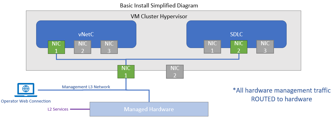
Topology Overview🔗
Below is the basic VM and hardware topology for reference.
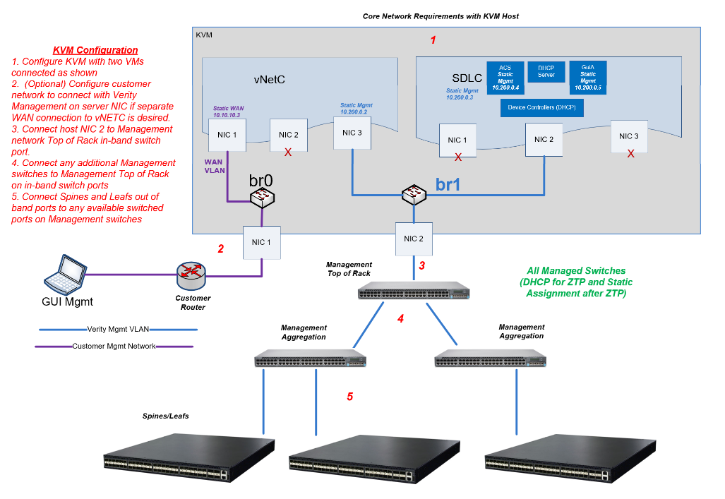
Recommended Network Management Architecture🔗
Each system requires a management subnet that can support 4 system IP addresses as well as 3 IP addresses per managed switch. The breakdown is as follows:
| IP address Allocations for Management Network | Component | Allocation |
|---|---|---|
| Verity System components | vNETC LAN side, SDLC, ACS, GuiA | 4 Static Addresses |
| Managed Switches | Verity Switch Controller | 1 Dynamic Address per switch |
| Managed Switches | Switch in ZTP Process | 1 Dynamic Address per switch |
| Managed Switches | Switch Post ZTP Process | 1 Static Address per switch |
The orchestration platform (vNETC) is configured on the customer’s network with one static IP address to be accessed by users.
The following diagram shows the recommended management network architecture. Variations are possible based on individual customer’s network needs. A second diagram follows with a version showing only one connection to the vNETC.
Prerequisites🔗
- vNetC
- Resolvable, fully qualified domain name
- Static IP address, gateway, DNS servers
- Valid Verity license
-
SDLC
-
IP addressing per table above
NOTE: Must be routable to the vNetC
-
-
Devcice Controllers (within SDLC)
-
IP Addressing per table above.
NOTE: The diagram above shows that the controllers are bridged to NIC 2 of the SDLC. The IP MUST be on the same VLAN/subnet as the SDLC.
-
-
KVM
- Compute resources meeting Verity requirements based on the number of switches being managed. See Resource documentation for computing CPU and memory needs.
- Virtual Switch
- The vNetC and SDLC should be on the same bridge or at minimum they must be routable.
- Routable or switched network between Verity components and managed switching devices
- If using a router or firewall between Verity and the switches, the following ports must be allowed to pass.
- Port 8080 for gNMI
- Port 80 - HTTP
- Port 443 - HTTPS
- Port 22 - SSH
- If using a router or firewall between Verity and the switches, the following ports must be allowed to pass.
Obtaining the vNetC and SDLC VM Images and Files🔗
Obtain the following files from BeyondEdge:
| Description | Filename Example | File Type | Notes |
|---|---|---|---|
| vNetC VM Image | vNetC-x_x_x_x.qcow2 | KVM qcow | Resources including vCPU and memory should be adjusted based on resource needs documentation. Networking will need to be altered to the correct bridge names used in the server |
| vNetC “core” Upgrade | core-x_x_x_x- full.tar | Tarball | vNetC needs to be updated via GUI SD-Admin immediately after configuration and boot |
| SDLC VM Image | SDLC-x_x_x_x.qcow2 | KVM qcow | Resources including vCPU and memory should be adjusted based on resource needs documentation. Networking will need to be altered to the correct virtual switch names used in the server |
| Firmware Upgrade Package | firmware-x.x.x.x.tar | Binary | SDLC should be upgraded via system upgrader immediately after configuration and boot |
| License | license.cms or sitexxxxx.tar | License file | Is uploaded using GUI |
| XML Parameters | vnetc.xml, and SDLC.xml | xml | Default files are provided and are edited during the installation process |
🔗
Creating the Virtual Machines🔗
The following instructions explain how to create virtual machines for both the vNetC and SDLC.
-
Copy vnetc and sdlc qcow and xml files to host (root directory):
files: vnetc.qcow2, SDLC.qcow2, vnetc.xml, and SDLC.xml
-
Make sure you have the bridge name from host for VMs:
nmcli connection show
-
Edit xml files (vnetc.xml and SDLC.xml) to have bridge name on the correct interfaces, number of CPU, and number RAM needed for each VM. Example:
`
<memory unit='KiB'\>**8388608**\</memory\>

<currentMemory unit='KiB'\>**8388608**\</currentMemory\>

<vcpu placement='static'\>**8**\</vcpu\>

<interface type='bridge'\>

<source bridge=**'br0'**/\>

<interface type='bridge'\>

<source bridge=**'br1'**/\>

<model type='virtio'/\>
`
-
Adjust xml file for Linux variants
- For Centos and Redhat
`
<devices>
<emulator>/usr/libexec/qemu-kvm</emulator>

<os>
<type arch='x86_64' machine='pc-i440fx-rhel7.6.0'>hvm</type>
`
- For Ubuntu
`
<devices>
<emulator>/usr/bin/qemu-system-x86_64</emulator>

<os>
<type arch='x86_64' machine='pc-i440fx-jammy'>hvm</type>
`
-
Move qcow (vnetc and SDLC) to /var/lib/libvirt/images directory
-
Define VMs using the edited xml files:
virsh define vnetc.xml
(Domain 'vnetc' defined from vnetc.xml)
virsh define SDLC.xml
(Domain 'SDLC' defined from SDLC.xml)
-
Set VMs to autostart on boot:
virsh autostart vnetc
(Domain 'vnetc' marked as autostarted)
virsh autostart SDLC
(Domain 'SDLC' marked as autostarted)
-
Start vnetc VM
virsh start vnetc
(Domain 'vnetc' started)
Configure the vNetC from the Console🔗
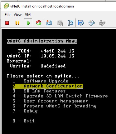
This step requires you to configure the vNetC with an IP address and Fully Qualified Domain Name (FQDN). To do so, you need to open the VM console: virsh console vnetc
The VM console appears. The vNetc initialization may take several minutes. While waiting you can press Enter and wait for login prompt.
- Login to the vNetC with username admin and password vnc1234. Enter a new password if prompted. If not prompted for the password, you can continue to use the default password or change it with the passwd command.
-
In the Admin Menu, select Network Configuration. Press Enter.
-
Select FQDN (Fully Qualified Domain Name). Press Enter and set to the desired Fully Qualified Domain Name. If the field is prepopulated, it is required that you replace the default text with your own FQDN.
- Verify that WAN IP DHCP is disabled. If WAN IP DHCP is enabled, disable it using the menu.
- Select WAN Static IP Settings, press enter.
- Enter: IPv4 Address and subnet in CIDR format (x.x.x.x/##) where x.x.x.x is the IPv4 address and ## is the CIDR subnet mask prefix
- Enter: Default Route (Gateway)
- Enter: DNS Server 1
- Enter: DNS Server 2 (if required)
- Return to the network configuration menu.
-
Save Settings
Follow the prompt and the VM will reboot with the new settings configured.
Install the License and Upgrade to the Latest vNetC Core Software🔗
Open SD-ADMIN in your web browser. This is required and not optional. Upgrade the vNetC Core software via the vNetC Web Administration.
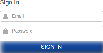
- Use Chrome Web Browser to access the vNetC IP address that was just configured.
-
At the login prompt enter username admin and the administration password configured in the menu during installation. These are the credentials you entered in step 3 of Configure the vNetC from the Console.
-
From the Admin web page, select the Software Packages and Licensing section by double clicking and zooming in.
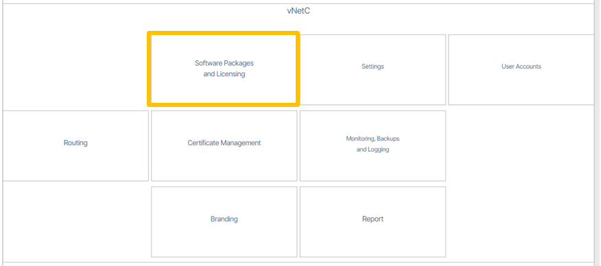
-
Select License

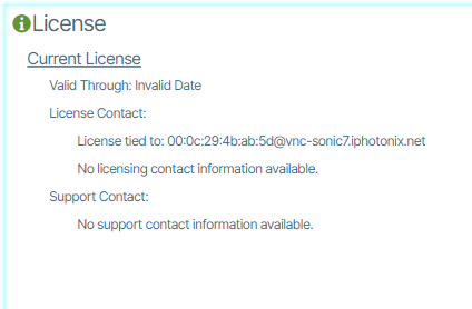
-
When the window appears, record the information on the Licensing tied to line. Provide this information to BeyondEdge to obtain your license file.
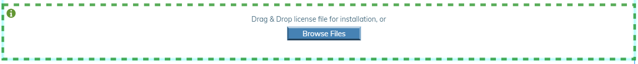
-
After you obtain your license.cms file you are required to upload it to the application. Use the drag and drop palette to upload the file or browse for the file. The license file may also be embedded in a \<filename>.tar file and this can also be directly imported and the system will extract the license.cms file.
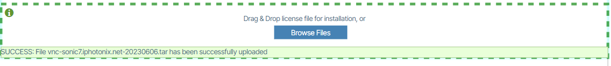
After you upload the file make sure a success message is presented.
After you upload the license, a tab titled Verity appears at the upper right of the screen (refresh the page if you do not see the tab). Click Verity and let the screen populate. Run migrations if prompted.
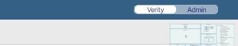
After the Verity window has fully completed populating select the Admin tab. Select Software Packages and Licensing and click vNetC Packages.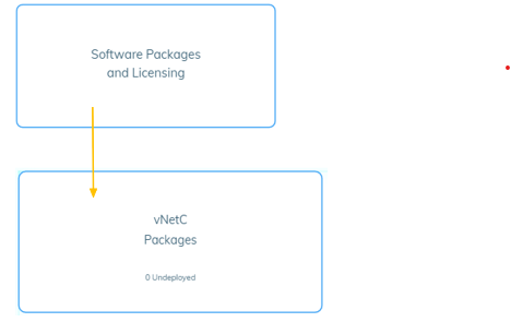
Using the Browse Files (or drag and drop) field, import the vNetC Core Upgrade file provided by BeyondEdge.

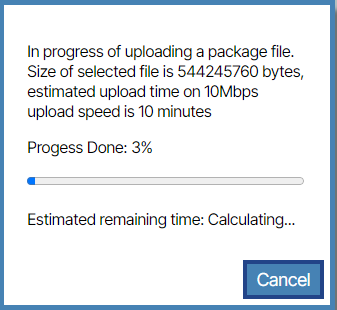
When the process is complete you are presented with a success message. .
.
Click the Deploy button ![]()
![]() .
When prompted to continue, click Yes. The software updates.
.
When prompted to continue, click Yes. The software updates.
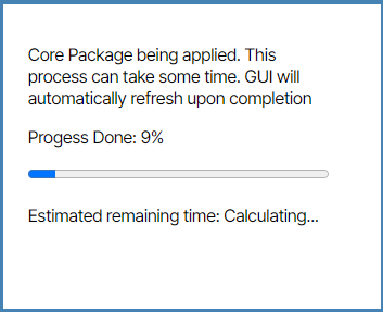
You may see an error titled Fatal Error WebSocket Error: Connection lost -2 appear, this is normal. The browser may temporarily say that the site cannot be reached. When the process is done the landing page will render.
-
Return to the SD ADMIN Menu on the console (If you are logged out, log back in and use the
virsh console vnetc menu command).
-
Select 3 - SD-LAN Features.
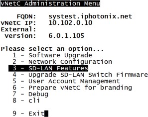
-
Select 8 – Place system in Data Center mode. Check that the field is set to ENABLED.
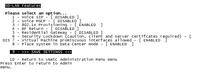
- Save Settings
When you are done importing the vNetC license and software update(s), shut the VM down using this command: virsh shutdown vnetc
Later, after you install the SDLC VM, you will restart the vNetC.
Configure the SDLC from the Console🔗
The SDLC must be configured with a Static IP address and the vNetC FQDN.
virsh start SDLC
(Domain 'SDLC' started)
virsh console SDLC
The console appears.
Starting interactive CLI.
Main#
Main# admin
Main/ administration# wizard
Active hostname is ivn-8680
Configured hostname is ivn-8680
Do you want to modify the hostname ? [y/n] (q to quit): y
Enter new hostname: SDLC
hostname entered is SDLC.
Do you want to change the current hostname (y/n): ? y
hostname SDLC set
Reboot required for changes to take effect.
Advertise the Site Management Vlan ? [y/n] (q to quit): n
Use DHCP for management uplink configuration ? [y/n] (q to quit): n
Enter MGMT IP [ex: 192.168.1.1] (q to quit): 10.26.11.251
Enter default gateway IP/Prefix in CIDR format [ex: 192.168.1.1/24] (q to quit): 10.26.10.1/23
Enter ACS IP [10.26.11.252] (q to quit, y to accept, s to skip): y
Enter GAIA IP [10.26.11.253] (q to quit, y to accept, s to skip): y
Enter DNS server [ex: 192.168.1.1] or Enter for none (q to quit): 10.26.10.17
Enter comma separated NTP server(s) [ex: 8.8.8.8,10.200.102.44 ; maximum 5 servers] or Enter for none (q to quit): 10.26.11.254
Enter vNetC FQDN or IP (q to quit): 10.26.11.254
The ACS connection path can either be entered as a complete URL, or, IP/protocol/port
Do you want to enter ACS as URL (e.g. http://TR069User:acspassword@10.102.0.13:5555/tr69/cwmp ? [y/n] (q to quit): n
Enter ACS FQDN or IP (e.g. 10.102.0.13 ; leave blank to use ACS IP or q to quit):
Enter ACS connection protocol ([1=http , 2=https] or q to quit): 2
Enter ACS connection port number (e.g. 5555 ; leave blank to use defaults (http=5555 , https=5554) or q to quit):
The VCF connection path can either be entered as a complete URL, or, IP/protocol
Do you want to enter VCF as URL (e.g. https://10.102.0.15/download/direct/file ? [y/n] (q to quit): n
Enter VCF FQDN or IP (e.g. 10.102.0.15 ; leave blank to use vNetC FQDN or q to quit):
Using vNetC FQDN.
Enable DHCP on management VLAN ? [y/n] (q to quit): n
***** Requested IP Configuration *****
vNetC @ : 10.26.11.254
ACS URL : https://TR069User:acspassword@10.26.11.252:5554/tr69/cwmp
Gateway : 10.26.10.1/23
Host IP : 10.26.11.251
ACS IP : 10.26.11.252/23
GAIA IP : 10.26.11.253/23
DHCP server : disabled
Domain Name Server : 10.26.10.17
NTP Server : 10.26.11.254
VCF URL : http://10.26.11.254/download/direct/file
**************************************
This will remove all previous configuration. Continue ? [y/n] y
Reboot is required for any changes to take effect.
Main/ administration# reboot
Start up the vNetC (this takes a few minutes):
virsh start vnetc
Open the GUI and select Admin in the top right. Select the Settings tile 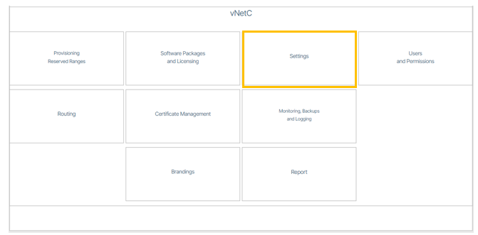
Set up the Management VLAN used to access the Management network. This field is required even if your management switches are untagged connections. Note: If untagged select “Managed on Native VLAN” checkbox.
In Permissible IP Address Ranges on Managed Devices enter the relevant IP address range (IP address and Mask).
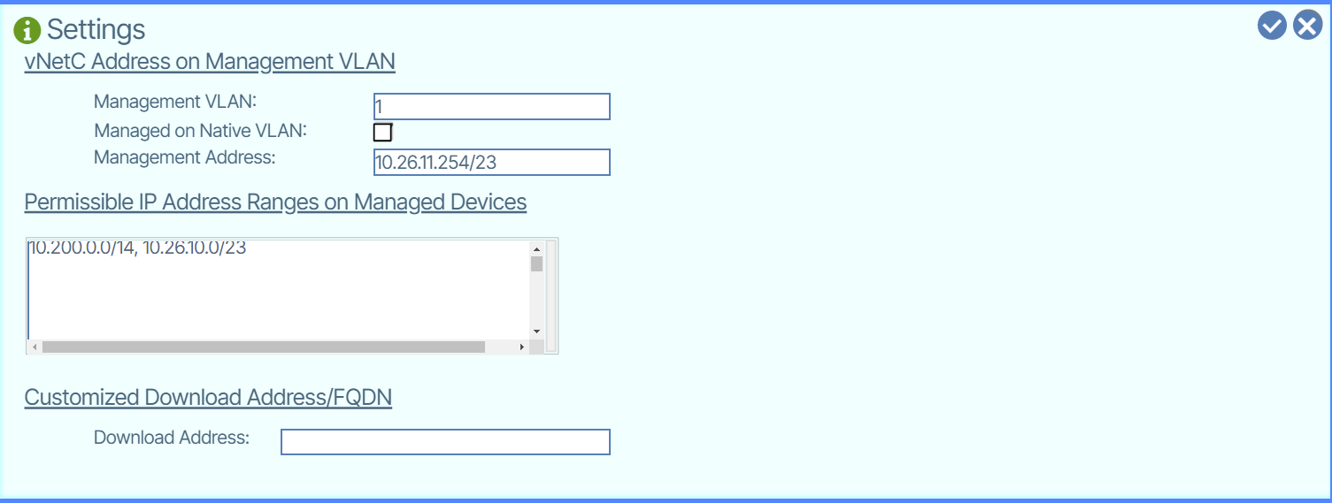
Click the checkbox icon  to save your settings.
Go to the Verity tab. If a beige notification box appears in the lower right, click it to close it.
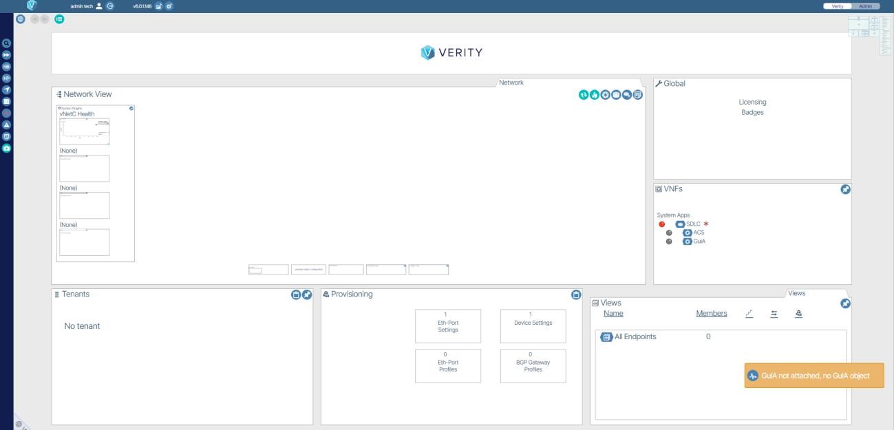
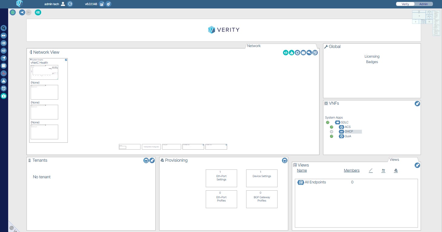
Wait until the process is finished. The application landing page resembles the image below when all processes have been completed.
Update SDLC🔗
Double click the Admin tab, double click Software Packages and Licensing. Double click Firmware Packages. Select and place the SDLC Binary Firmware Upgrade firmware file on the Drag & Drop area or use the Browse Files button to select the file.
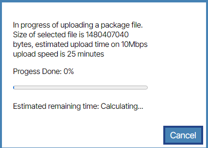
When uploaded, you are prompted with a green success message.
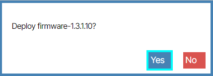
Deploy the firmware by clicking the Deploy ![]() button.
button.
A validation message appears. Click Yes.
Click the Verity tab.

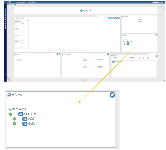
Double click the VNFs window 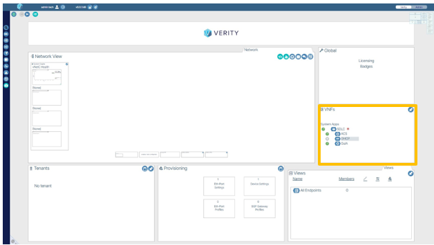 .
.
Double click the SDLC section 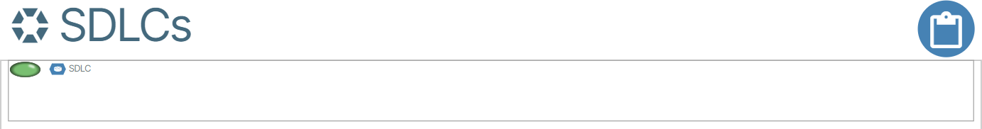 .
.
Double click the box with the title of SW Version 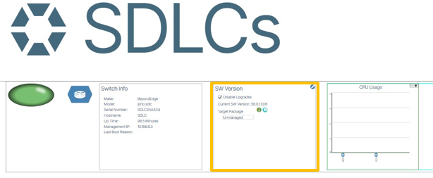 .
.
Set the Target Package field to the Firmware version and uncheck the box titled Disable Upgrades.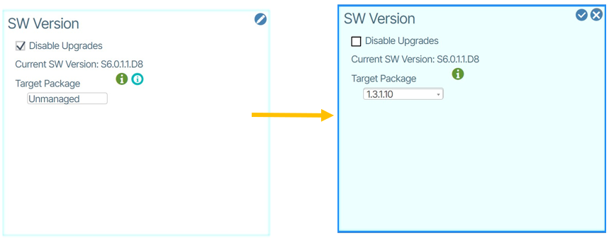
Click the Check button  .
.
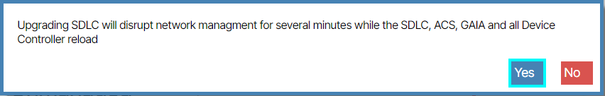
Click Yes to the validation message.
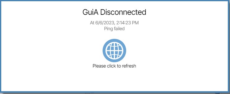
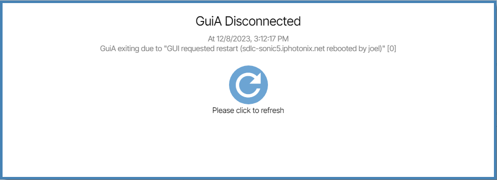
In the window that appears titled GuiA Disconnected, click the icon to refresh.
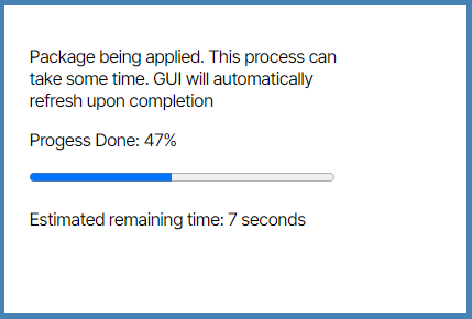
Let the process complete.
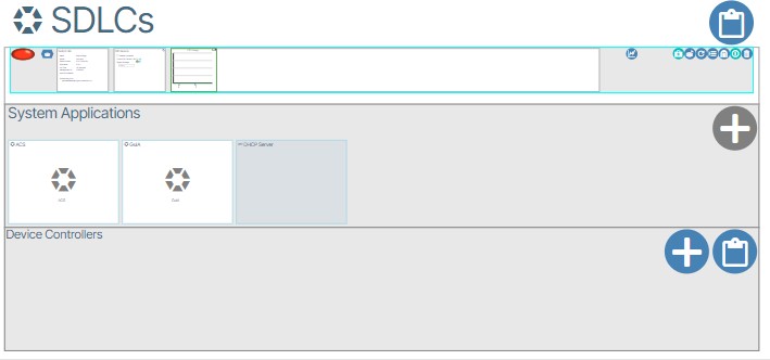
When the window appears the initial state of System Applications are offline. This is expressed by their red LED icons.
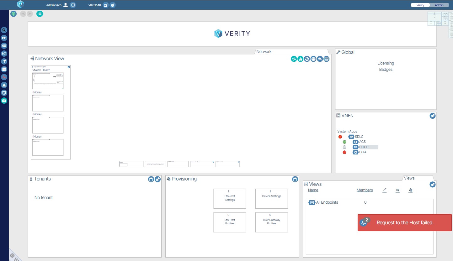
When the System Applications come online their LED icons render green. This may take up to 5 minutes.
Site Certificate🔗
In order to avoid having to accept the self signed certificate delivered with the system you will need to add a server.pem file to the system. This will need to be obtained from your internet domain administrator.
- Click on the Admin tab.
- Select Certificate Management box.
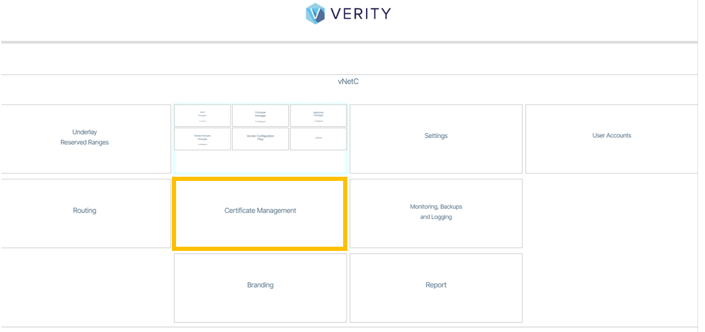
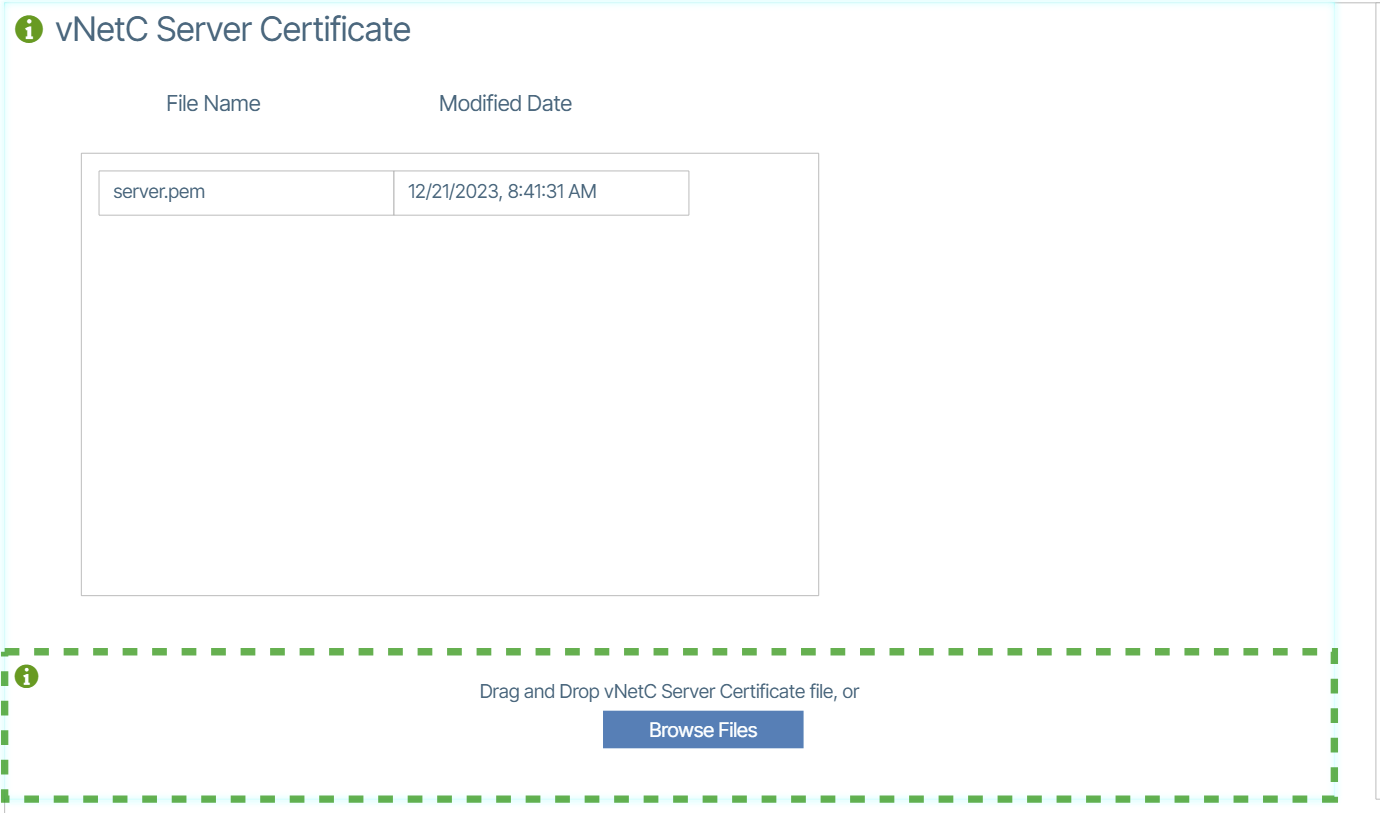
- Click on vNetC Server Certificate box.
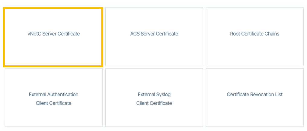
- Drag and drop the server.pem file.
The installation and updates of Verity for Cloud software components is now complete.