Managing Devices🔗
Adding new devices is a multistep process:
graph LR
  A[1. Create Device Controller] --> B[2. Create Switchpoint] --> C[3. Physical Switch Preparation] --> D(Device Boot - MGT Network) --> E[4. Connect Switch to Peers];
  style D fill:#c4dbec,stroke:#333,stroke-width:2px;
Device Controllers🔗
The Device Controllers object is used to create the interface between the Verity application and the switch device. Based on the LLDP capabilities of the switch, it can be automatically discovered in the network topology, or it can be statically located. For systems containing many devices, the configuration of the Device Controllers can be imported/exported from the Import/Export tool bench. 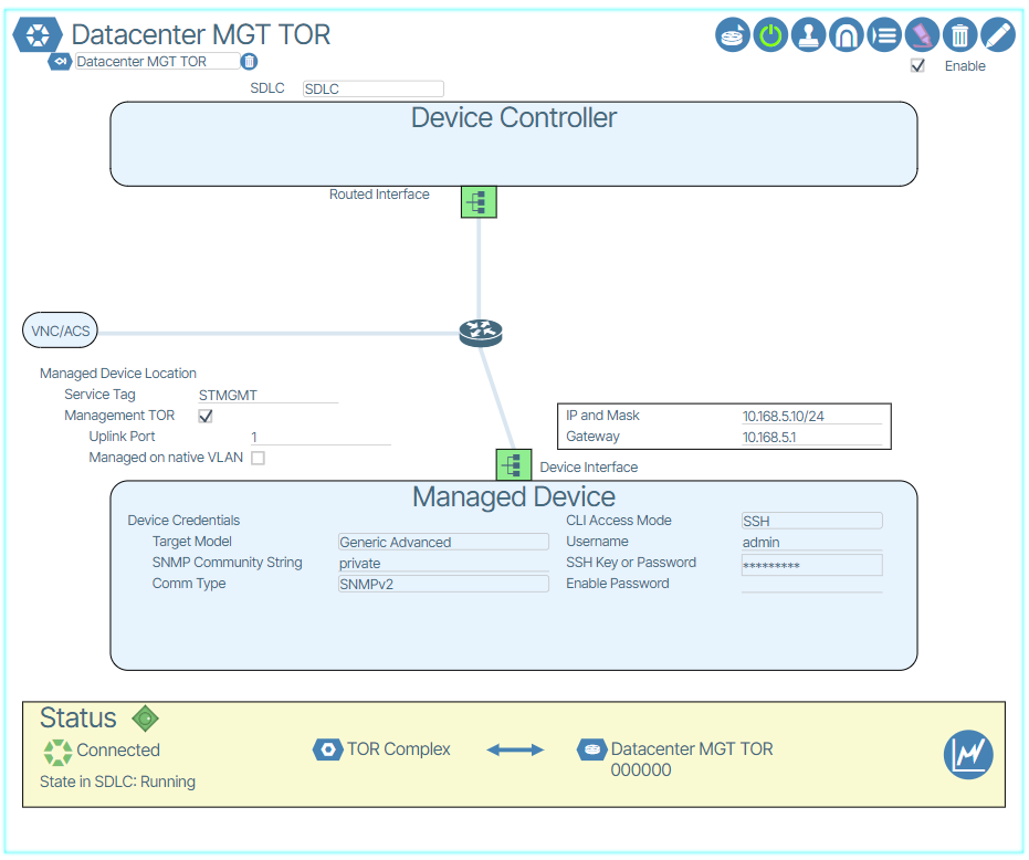
Create a Device Controller🔗
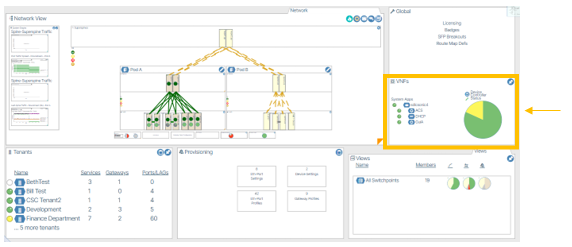
- From the world view, double-click the VNFs tile.
- Click the Add Device Controller (
 ) button.
 - Enter a name for the Device Controller.
- Submit the form by clicking the Save (
 ) button.
 - The new Device Controller edit window will appear.
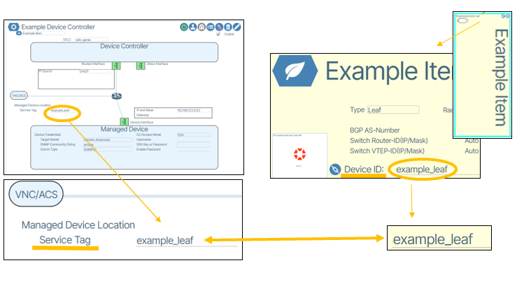
- Enter the information displayed in red highlights in the image.
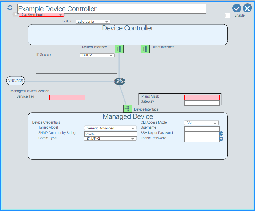
- Enter the Service Tag in the proper field. This value must be either the chassis-id or the hostname of the LLDP from the managed device. The identifier is used to detect connections between managed devices.
- Etner the IP address and netmask in the proper field.
- Enable the check in the Enable box.
- Click the Save button to finish creating the device controller.
Switchpoints🔗
A Switchpoint is a logical location for a device in the network. By designing a network using Switchpoints, the logical design remains independent of specific devices, allowing an operator to insert a device into the switchpoint by referring to its serial number.
Create a Switchpoint🔗
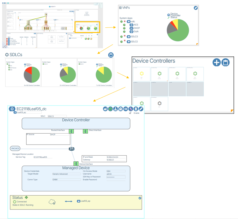
- Navigate to a Device Controller (World-view / VNFs / SDLCs / Device Controllers).
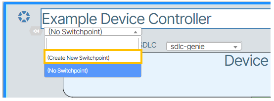
- Use the Switchpoint form field to create a Switchpoint.

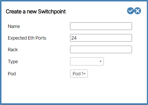
- In the prompt that appears, fill in the fields and submit the form.
- Enable the Switch Controller by checking the Enable field and clicking the check button icon.
Verify Hardware Identifier🔗
In the Device Controller the value titled Service Tag must match the value in the Switchpoint titled Device ID.
Physical Switch Preparation and Connection.🔗
Before you connect the switch to the network you must access the console and force the switch into ONIE mode and uninstall any current operating system.
When complete, connect the management port of the new device to the Out-of-Band Management network. Then, connect the device to the other relevant spine/leaf switches needed to integrate the device into the system.
Zero Touch Provisioning🔗
Verity’s ZTP feature is a way to remotely set up switches without having to manually configure them on a hop-by-hop basis. The process consists of two steps: ONIE Boot process and ZTP Provisioning portion.
The ONIE process starts when a switch boots up from the factory without a SONiC image and it connects to a remote server to download the necessary software image. The actual ZTP process starts with a switch that has SONiC loaded and a default configuration. The verity system creates a series of files that are used to prepare the SONiC switch with a minimal configuration to communicate with the Device controllers within Verity. DHCP options on the Verity SDLC server tells the switches the location of the remote server (vNetC) where the required files are stored. The system supports ZTP for both the management and spine/leaf switches.
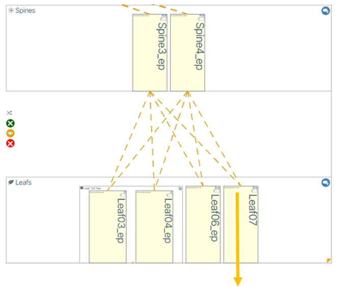
Adding Leaf or Spine Devices🔗
- Enable the world view by clicking the World icon.
- Click the Add Preprovisioned Switch icon.
- Enter the name of the switch.
- Set the number of Expected Ethernet Ports.
- Set the Rack text (Optional).
- Click-hold the type field and select Leaf or Spine.
- Set POD value. Click hold field with name POD.
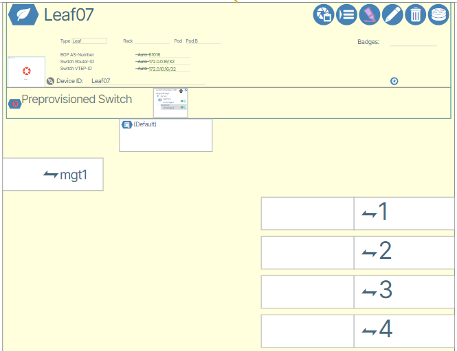
Preprovisioned Devices🔗
Preprovisioning lets the user set up the device before the hardware arrives. Zooming in allows the user to edit the details of the device.